Relays are foundational components in electronics and automation, acting as electrically controlled switches. Whether you’re building a smart home system, an industrial controller, or a DIY robotics project, understanding relays and relay modules is essential. Let’s explore what they are, how they work, and how to integrate them into your projects.
—
What is a Relay?
A relay is an electromechanical or solid-state device that allows a low-power electrical signal to control a high-power circuit. It isolates the control circuit (e.g., a microcontroller) from the load (e.g., motors, lights, appliances), protecting sensitive components from high voltages or currents.
How It Works
– Electromechanical Relays: These use an electromagnet to mechanically toggle a switch. When a small voltage is applied to the coil, it generates a magnetic field, pulling a metal armature to close or open the contacts.
– Solid-State Relays (SSRs): These rely on semiconductors (like optocouplers or transistors) to switch the load electronically, offering faster response times and no moving parts.
Relays are categorized by their contact configurations:
– SPST (Single Pole Single Throw): One circuit, two states (on/off).
– SPDT (Single Pole Double Throw): One input, two outputs.
– DPST/DPDT: Multiple poles for controlling separate circuits.
—
What is a Relay Module?
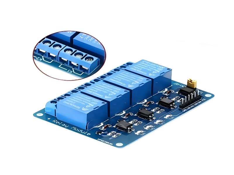
A relay module integrates a relay with supporting circuitry for easy use in DIY projects. Key features include:
– Optocoupler Isolation: Protects the control circuit from voltage spikes.
– Driver Circuit: Amplifies weak signals from microcontrollers (e.g., Arduino, Raspberry Pi).
– Status LEDs: Visual indicators for relay activation.
– Terminal Blocks: Screw terminals for secure load connections.
Most modules, like those from Motorobit, support common voltages (5V or 12V DC) and include multiple relays for multi-channel control.
—
How to Use a Relay Module
1. Wiring the Module
– Power Supply: Connect the module’s VCC and GND to a compatible power source (e.g., 5V for Arduino).
– Control Signal: Link the input pin (IN1, IN2, etc.) to a microcontroller’s digital output.
– Load Connection: Attach the high-power device (e.g., a lamp) to the relay’s COM (common) and NO (Normally Open) terminals.
Example:
– To control a 120V AC lamp with an Arduino:
– Arduino’s 5V → Module’s VCC
– Arduino’s GND → Module’s GND
– Arduino’s Digital Pin 7 → Module’s IN1
– Lamp’s live wire → COM terminal
– Lamp’s neutral wire → NO terminal
2. Programming the Control
Use simple code to toggle the relay:
“`cpp
void setup() {
pinMode(7, OUTPUT);
}
void loop() {
digitalWrite(7, HIGH); // Relay ON
delay(5000);
digitalWrite(7, LOW); // Relay OFF
delay(5000);
}
“`
3. Safety Tips
– Always disconnect power before wiring high-voltage loads.
– Use SSRs for high-frequency switching or silent operation.
– Ensure the relay’s current/voltage ratings match your load.
—
Applications of Relay Modules
1. Home Automation: Control lights, fans, or AC units via Wi-Fi/Bluetooth.
2. Industrial Systems: Manage motors, pumps, or conveyor belts.
3. Safety Cutoffs: Automatically disconnect power during overloads.
4. IoT Projects: Integrate with sensors (e.g., turn on a heater if temps drop).
—
Why Use a Relay Module Instead of a Bare Relay?
Modules simplify prototyping by handling isolation, signal amplification, and protection. For instance, Motorobit’s relay modules include built-in flyback diodes to suppress voltage spikes from the coil, a feature you’d need to add manually with a standalone relay.